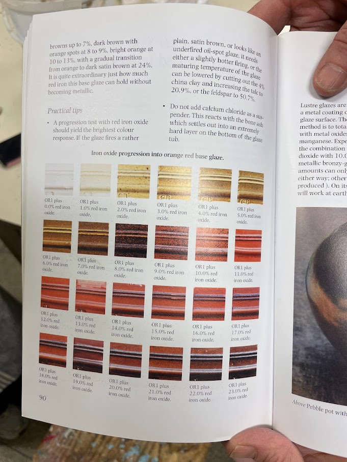
“Glazes: Cone 6” by Michael Bailey contains recipes for a set of beautiful mid-fire ceramic glazes. One of those recipes is a orange red iron glaze, ranging from yellow to brown and bright orange depending of the percentage of red iron oxide added to the base recipe.
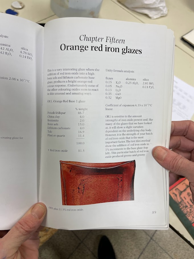
| Ingredient | % |
|---|---|
| Potash feldspar | 46.7 |
| China clay | 4.0 |
| Bentonite | 2.0 |
| Bone ash | 15.0 |
| Lithium carbonate | 4.0 |
| Talc | 16.9 |
| Quartz | 11.4 |
After preparing batches of the base glaze with various percentages of red iron oxide, we noticed that our glaze rather ranged from light to dark green and brown. The obtained colour looked great, but we were wondering why our glaze gave unexpected results.
Glazes are influenced by various factors including the clay body, firing technique, and temperature of the kiln. We wondered what changes we could make to our process as to obtain results that are closer to those of the book. The book itself gave us a hint:
If the glaze fires a rather plain, satin brown […] the maturing temperature can be lowered by cutting out the 4% china clay and increasing the talc […] or the feldspar […].
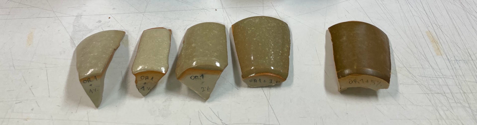
I decided to base my ceramics graduation project on a study of OR1 glaze variants:
- Cutting out china clay and increasing the talc;
- Cutting out china clay and increasing the feldspar;
- Using synthetic red iron oxide instead of natural red iron oxide.
Other ideas included:
- Using natron feldspar instead of potash feldspar;
- Using Bentone EW instead of bentonite.
In the end, we saw that increasing the talc made the glaze more matte whilst increasing the feldspar made it more shiny without really having a large impact on colour. What did have an impact on colour was the clay body used and the use of synthetic red iron oxide. By using synthetic instead of natural red iron oxide, the resulting glaze was closer to what we would expect from the book.
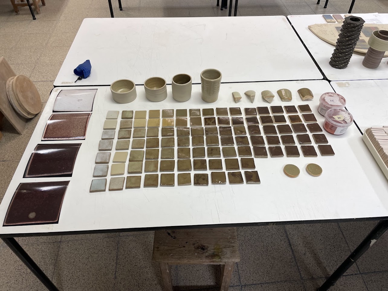
Glaze Preparation
We numbered each of the glaze variants and gave a unique identifier based on their percentage of red iron oxide. Glazes 0–19 correspond to the original recipe with natural red iron oxide ranging from 0% to 19%, 20–39 correspond to the altered recipe with increased feldspar, and so on.
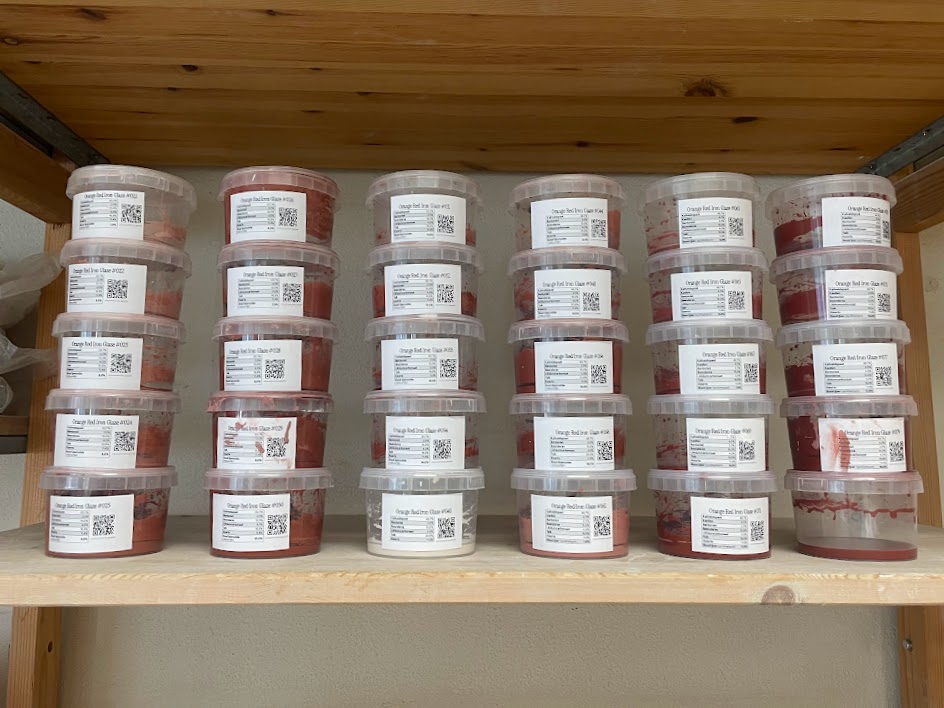
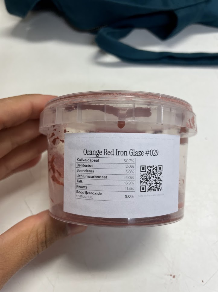
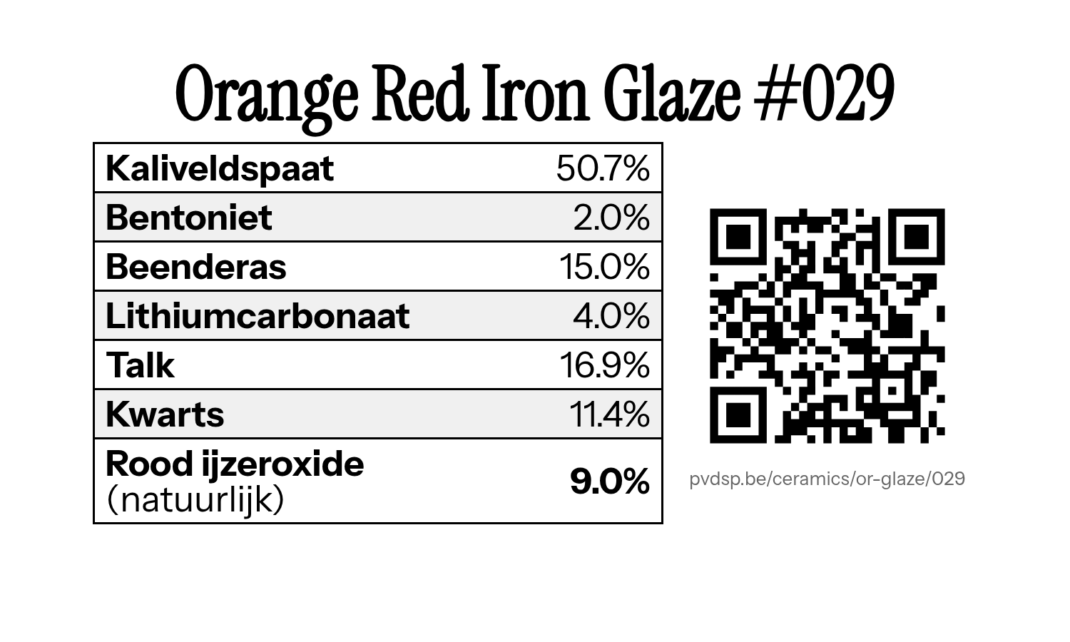
For this project, I repeatedly prepared 100g of each base glaze variant and added natural or synthetic red iron oxide. Each of these recipes get their own labelled tub with glaze identifier, the recipe, and a QR code that leads to a page with examples of that glaze.
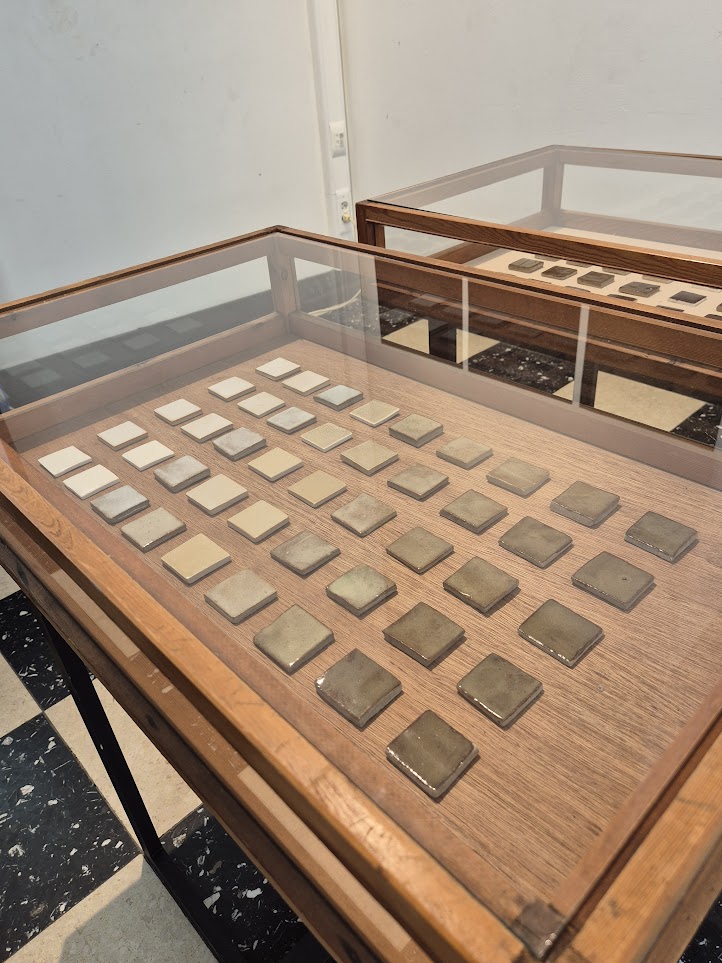
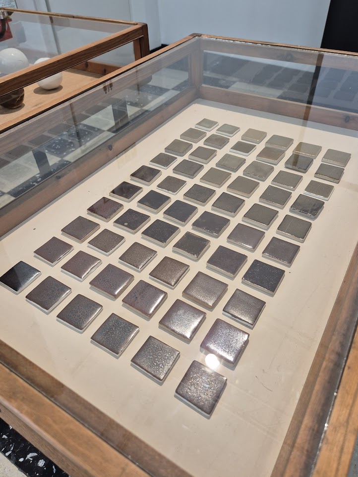
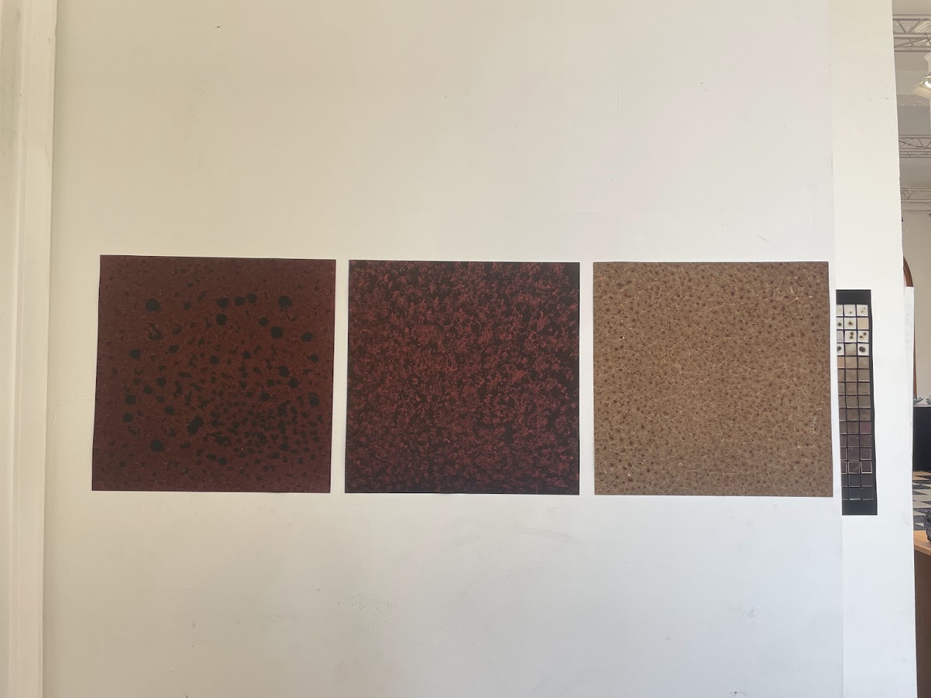
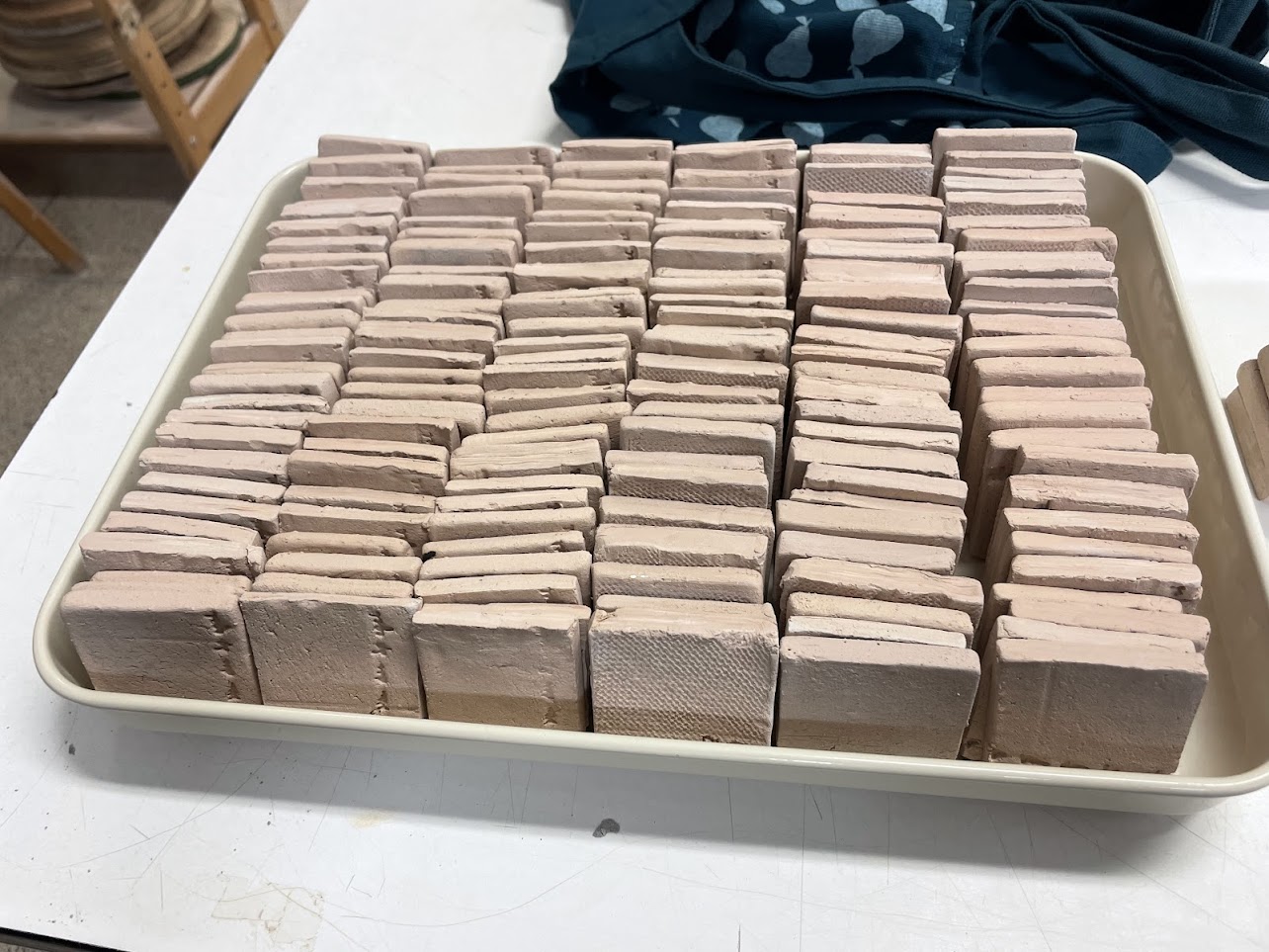
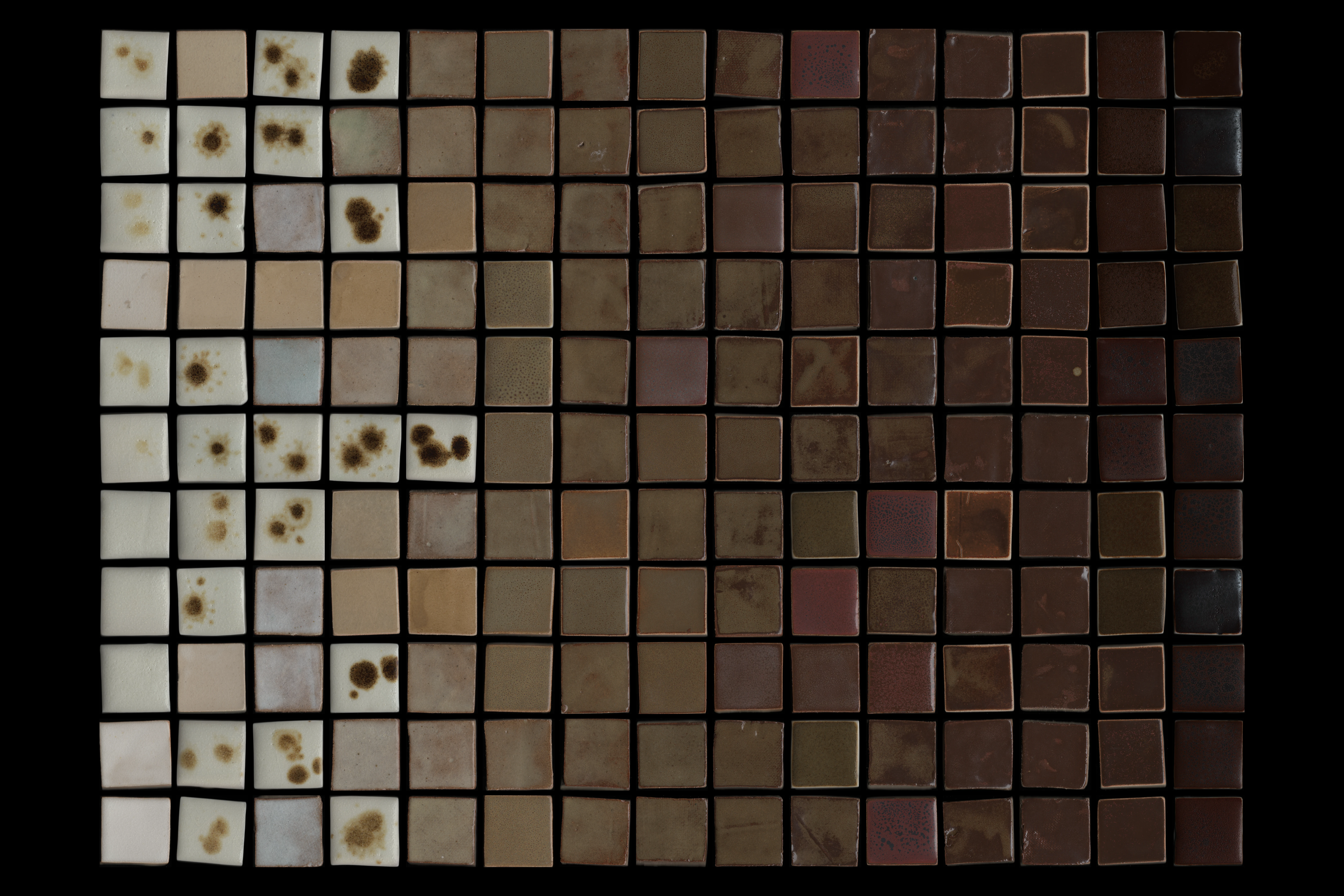
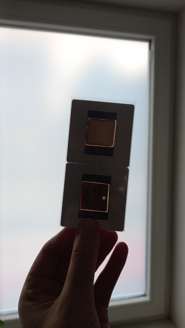
Test Tiles
Using a paint brush, we applied these different glazes on 5x5cm test tiles of various clay bodies: we used reclaimed clay, white clay, and porcelain tiles; all fired at 1230°C or 1240°C.
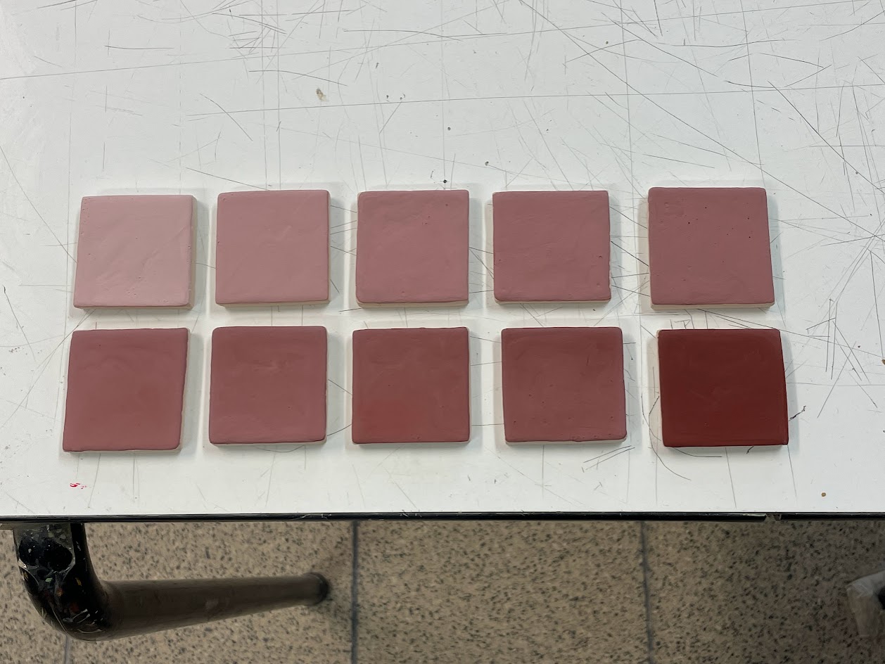
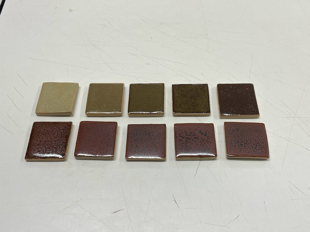
There’s a large difference in how these test tiles look before and after firing, going from a soft pink before firing to a range from green to red afterwards.
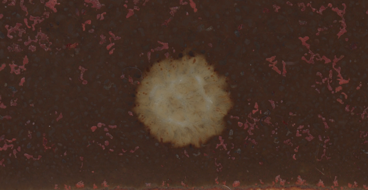
Splatters
During the preparation of one of the test tiles, I accidentally spilled a drop of one glaze over the tile of another glaze, which gave a surprising effect after firing.
I tried to replicate this afterwards with drops of high percentages red iron oxide glaze on a tile with the base recipe without any red iron oxide, but the results were not as expected:
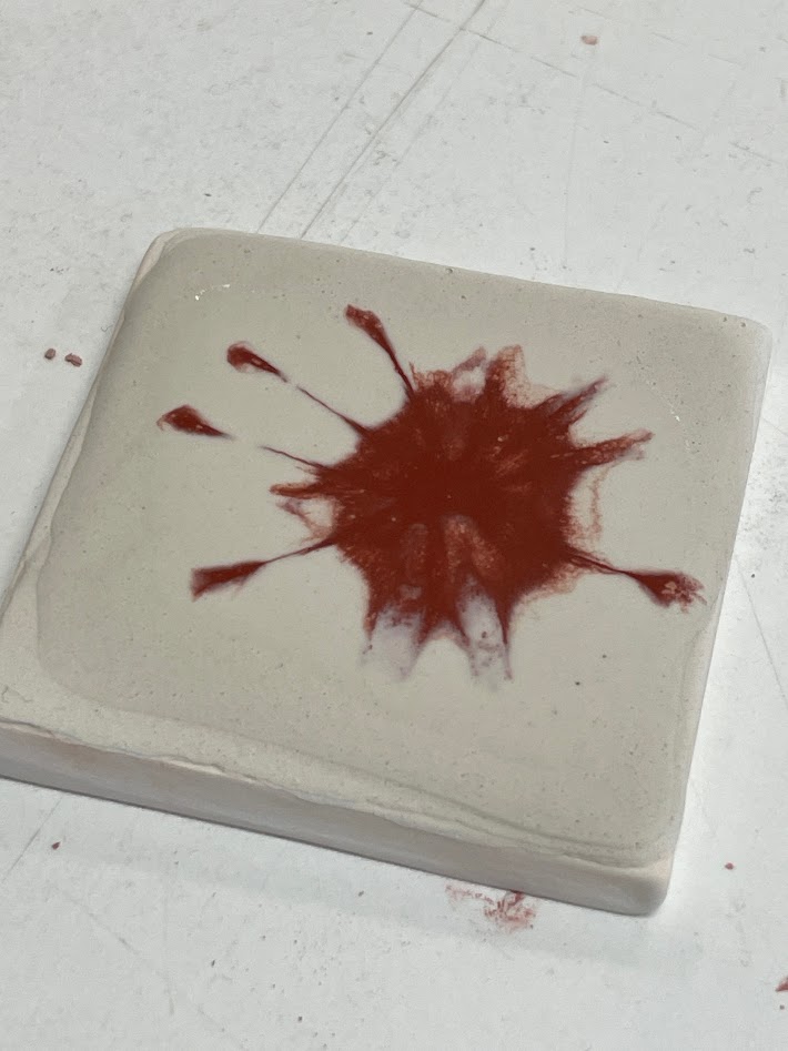
Because of this result, I abandoned the investigation of splatters and kept focusing on other glaze variants.
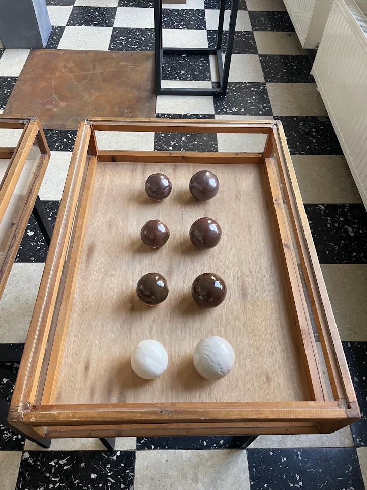
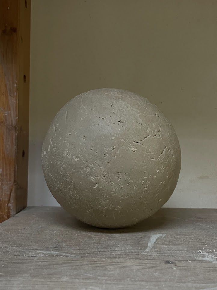
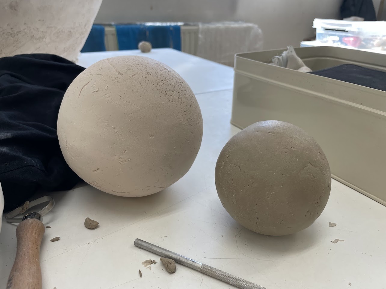
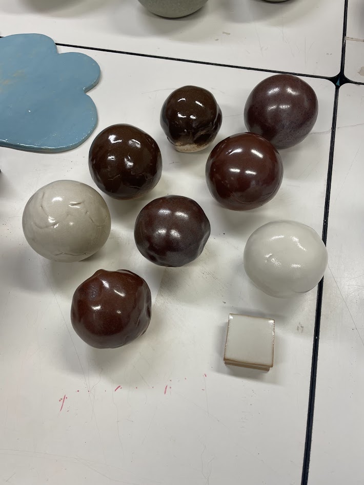
Test Spheres
Finally, we also applied these glazes on white clay and porcelain spheres using a spray booth to see what the glaze would look like on curved surfaces.
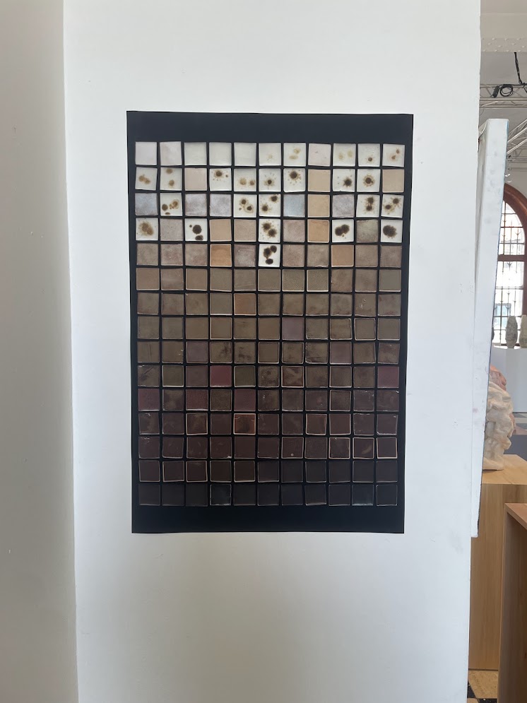
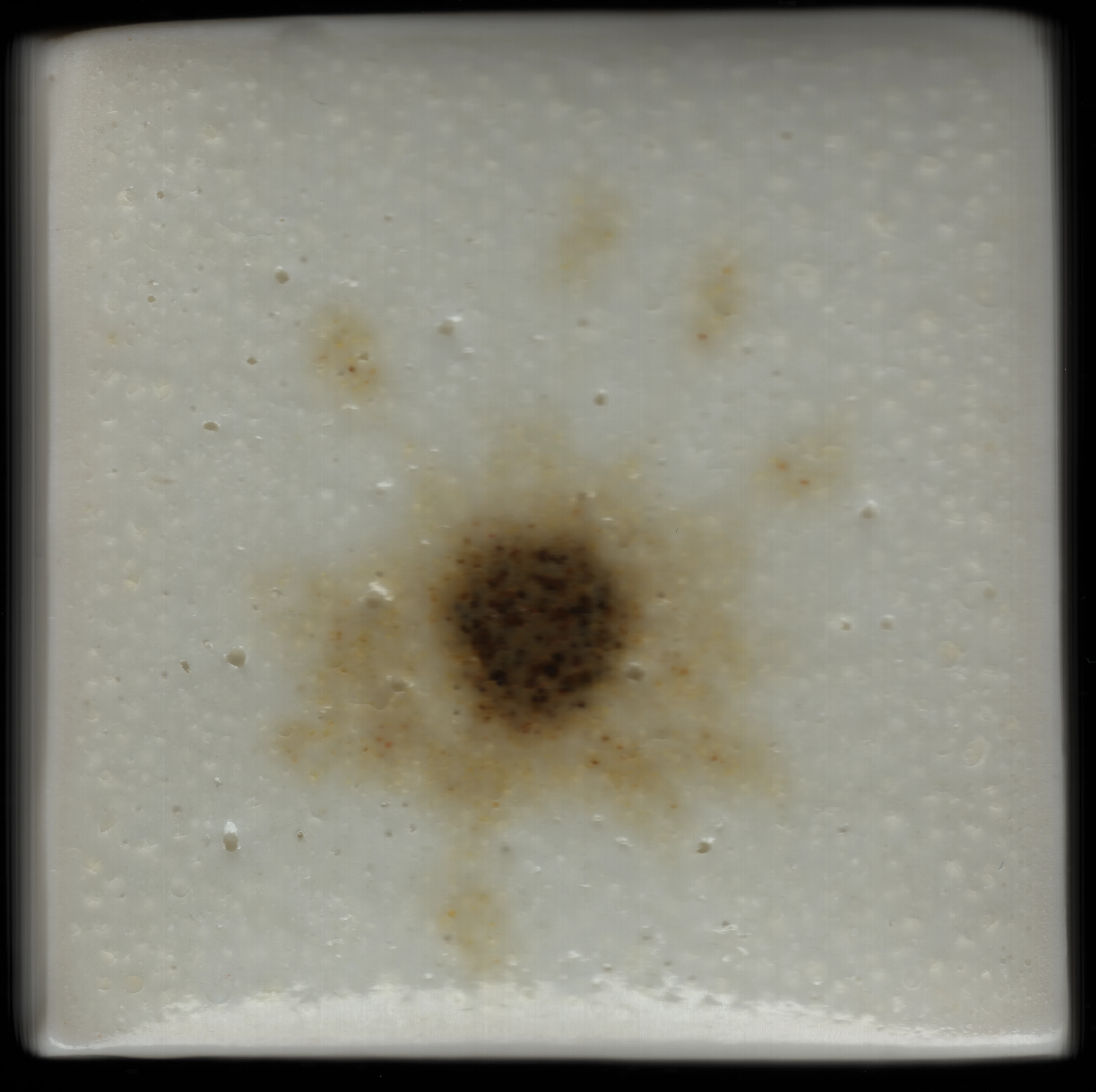
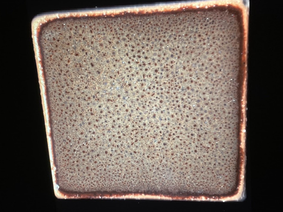
Glaze Scanography
A large part of this work was tile scanning on a Canon CanoScan LiDE 210 flatbed scanner to obtain a close-up of each test tile.
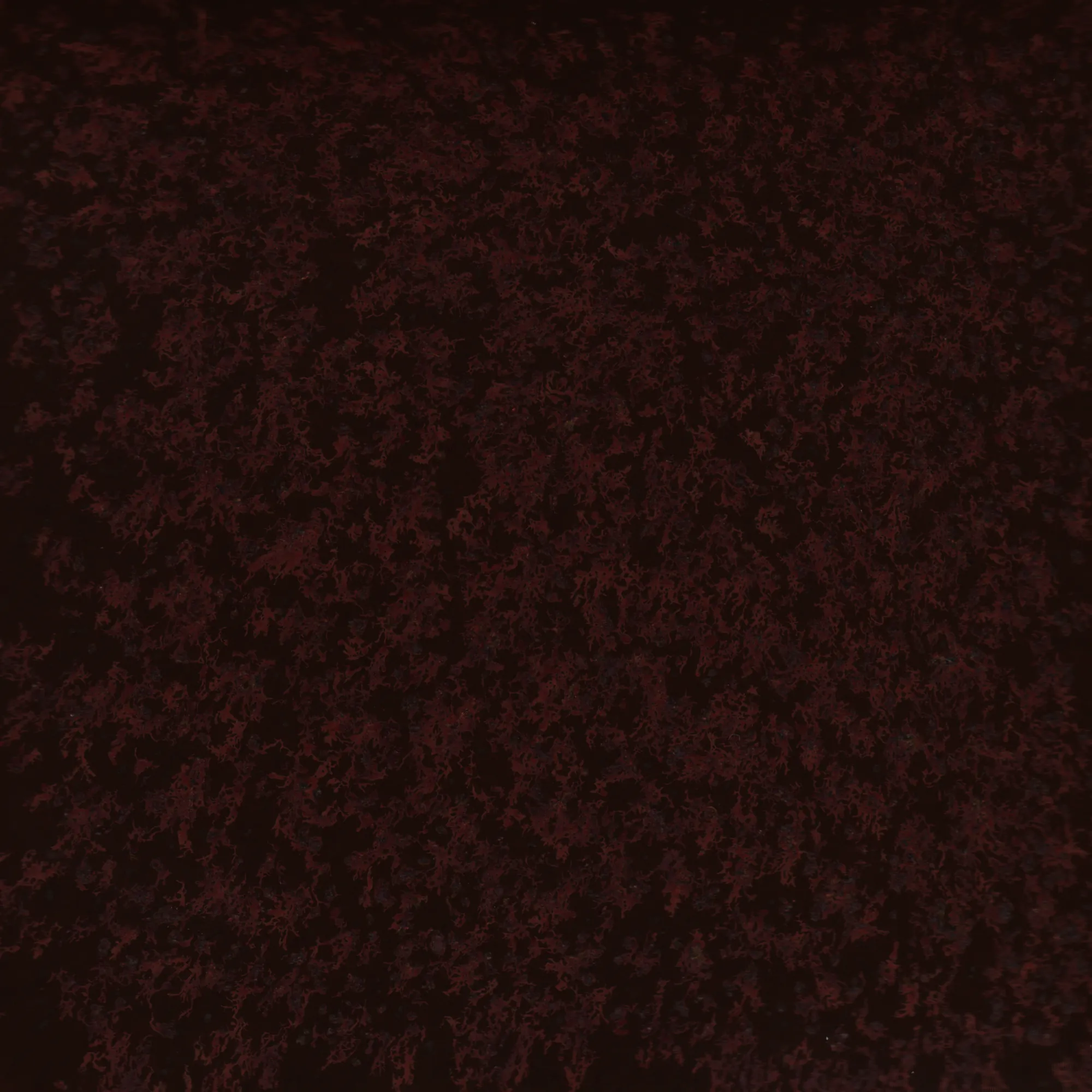
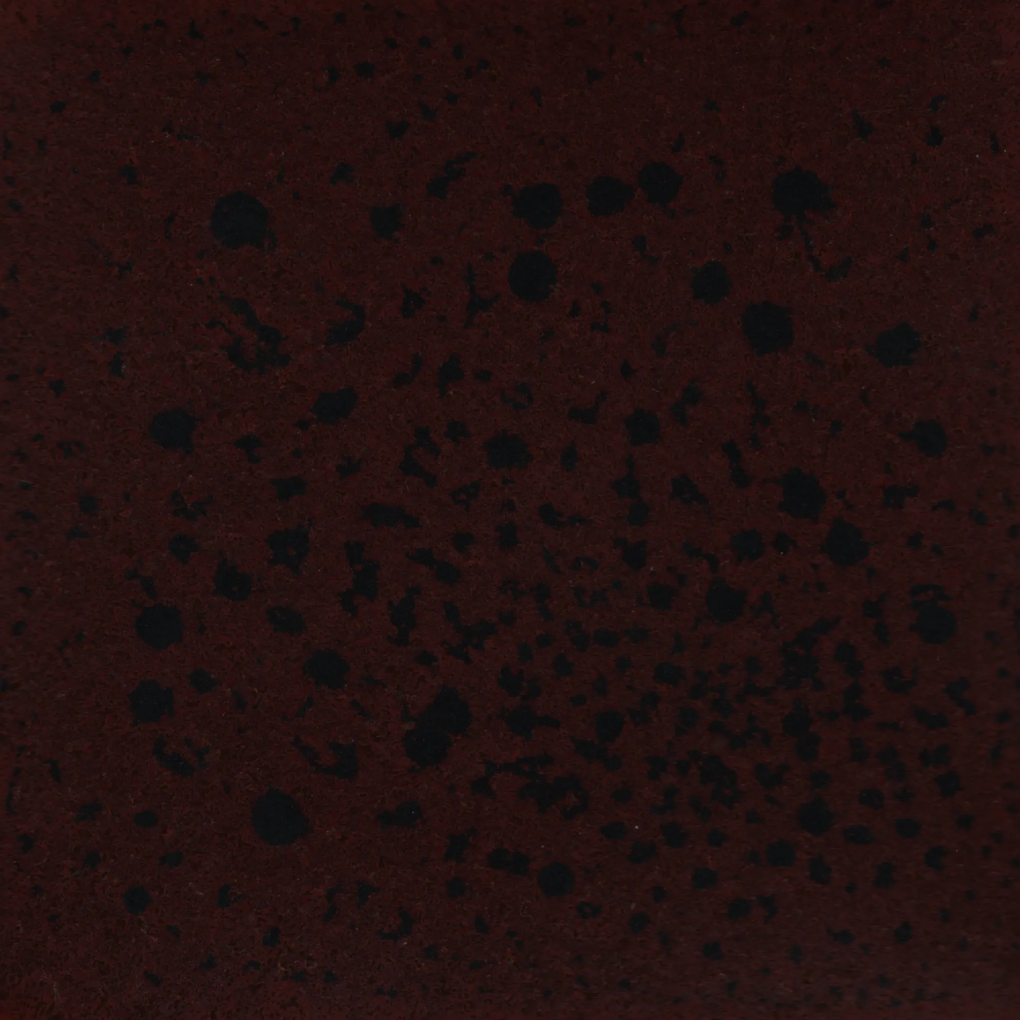
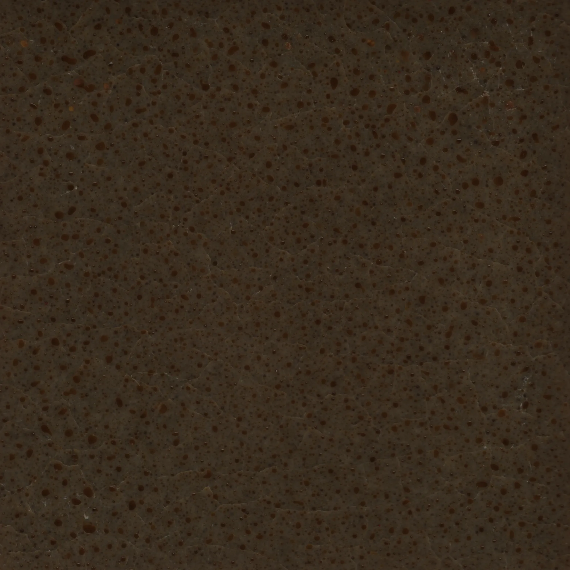
All tiles are visible here. Each scan links to its own recipe page, where you can see the recipe and other scans of the same glaze.
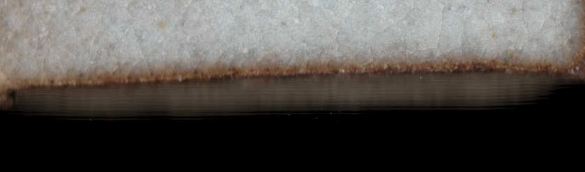
Some tiles are not perfectly flat and thus some spots look blurry when scanned because of a lacking depth of field of my flatbed scanner. This is especially visible at the edges of the tile. I’d love to replicate these scans on a CCD scanner and see if tile edges turn out sharper.
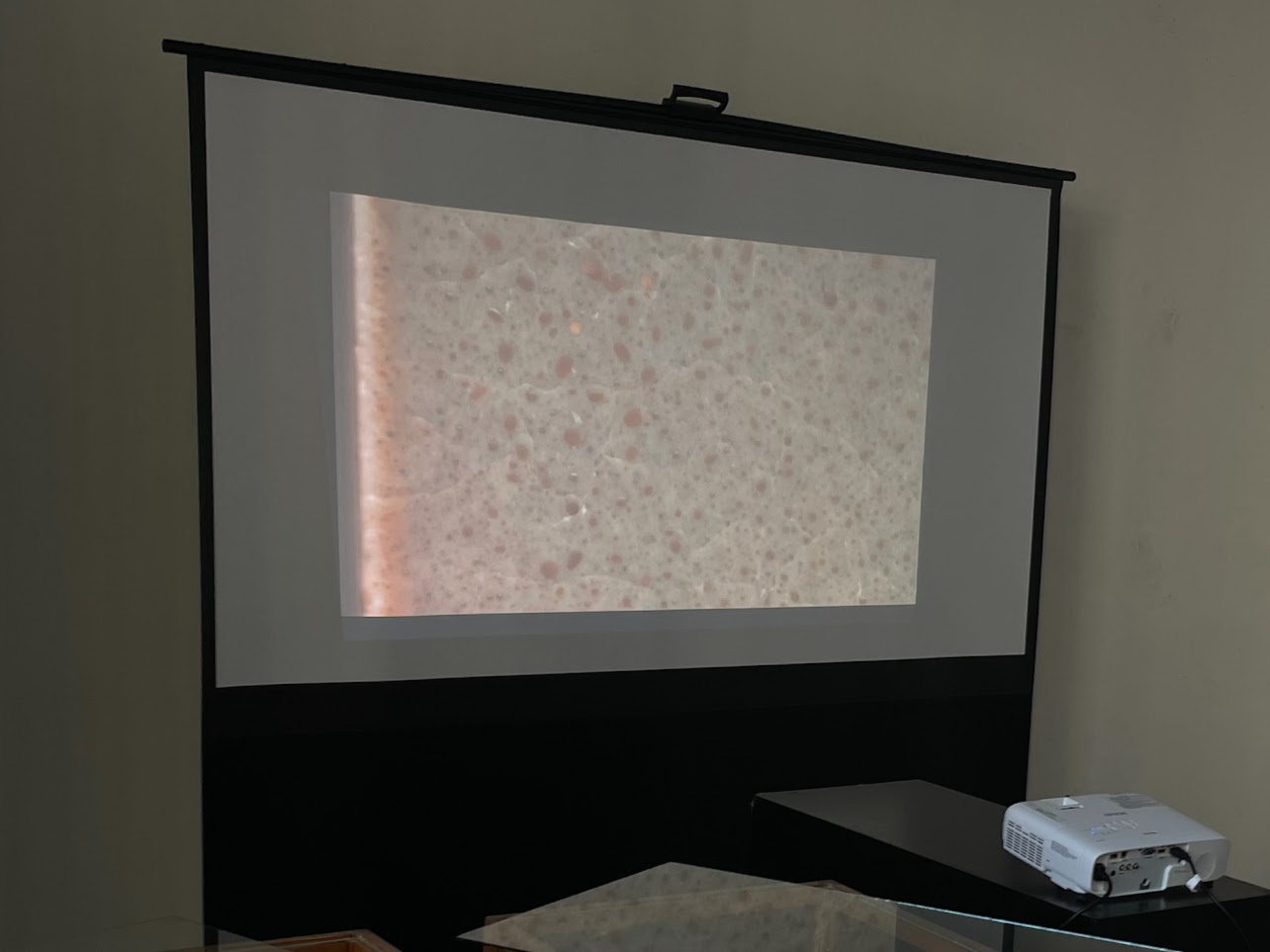
Projection
I initially wanted to display the tile scans using a cheap second-hand Elmo Omnigraphic 252, a carrousel slide projector. This specific model sadly does not have a built-in timer. Some shops sell universal interval timers which seem compatible with the projector, but these go for several times the price I paid for the projector itself.
I created my own WiFi-enabled timer allowing me to:
- Manually, but remotely, cycle through my slides;
- Automatically cycle through all the slides of the tray;
- Change the time interval of this cycling.
I tackled this project using a Wemos D1 Mini, soldering a 6-pin DIN connector, and struggling to make a basic electronics circuit containing a relay, diode, and transistor on a breadboard. This worked (and I learned a lot in the process), but in the end I had to abandon the idea of using slides for the presentation of my work because of time and budget constraints: the cost of ordering 80 slides with express delivery was not worth the novelty of using this slide projector.
Instead of going for the slide projector, I opted to create a moving image from a handful of scans by zooming in and sliding over the image. This video could then be displayed using a small media player connected to a beamer over HDMI.
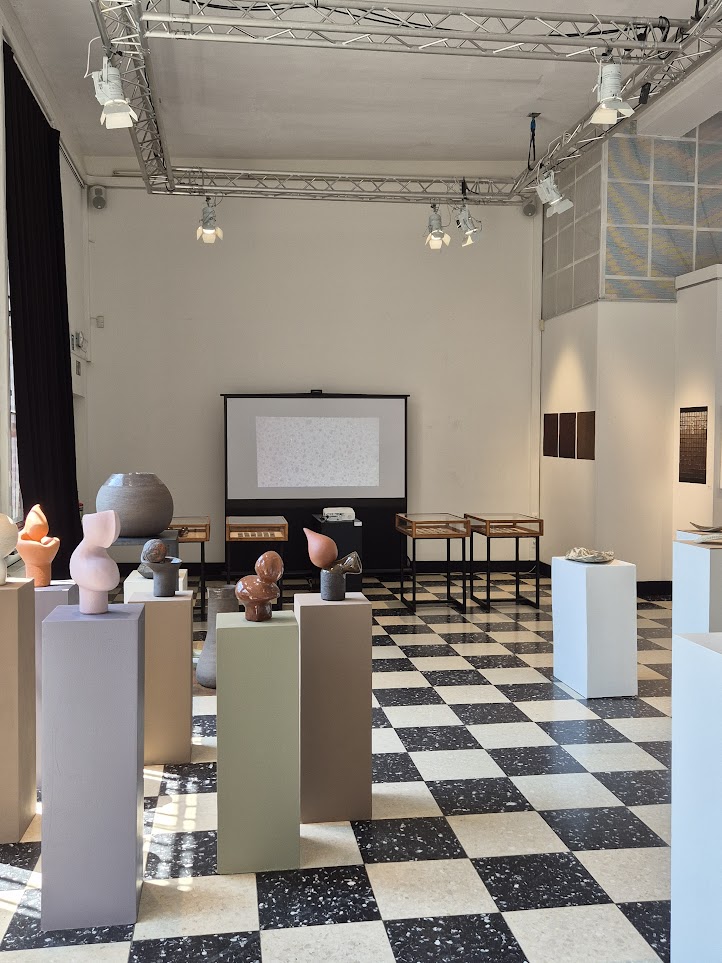
Exposition